


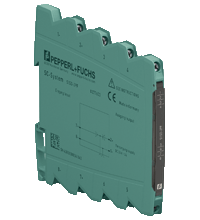
Switch Amplifier S1SD-1DI-1R
- 1-channel signal conditioner
- 24 V DC supply
- Input for 2- or 3-wire sensors or AC/DC voltage sources
- Relay contact output
- Timer function
- Configurable by DIP switches
- Connection via screw terminals

Quantity

Free Shipping
Purchase on Account

Please note: All product-related documents, such as certificates, declarations of conformity, etc., which were issued prior to the conversion under the name Pepperl+Fuchs GmbH or Pepperl+Fuchs AG, also apply to Pepperl+Fuchs SE.
Datasheet excerpt: Technical data of S1SD-1DI-1R
| General specifications | ||
|---|---|---|
| Signal type | Digital Input | |
| Supply | ||
| Connection | Power Bus or terminals 1-, 2+ | |
| Rated voltage | 16.8 ... 31.2 V DC | |
| Power dissipation | 0.6 W | |
| Power consumption | 1.1 W | |
| Input | ||
| Connection side | field side | |
| NAMUR sensor | ||
| Type | 2-wire | |
| Connection | terminals 5+, 6 | |
| Signal | acc. to EN 60947-5-6 (NAMUR) | |
| Sensor supply | 8 V | |
| Open-circuit | < 0.1 mA | |
| Switching point | 1.2 ... 2.1 mA | |
| Short-circuit | > 6 mA | |
| Input impedance | 1 kΩ | |
| Mechanical contact | ||
| Type | 2-wire | |
| Connection | terminals 5+, 6 | |
| Sensor supply | 15 V | |
| External supply | ≤ 32 V | |
| Switching point | 8 ... 10 V / 1.2 ... 2.1 mA | |
| Input impedance | 4 kΩ | |
| SN sensor | ||
| Type | 2-wire | |
| Connection | terminals 5+, 6 | |
| Sensor supply | 8 V | |
| Open-circuit | < 0.1 mA | |
| Switching point | 1.2 ... 2.1 mA | |
| Short-circuit | > 6 mA | |
| Input impedance | 1 kΩ | |
| 2-wire DC sensor | ||
| Type | 2-wire | |
| Connection | terminals 5+, 6 | |
| Signal | acc. to EN 60947-5-2 | |
| Sensor supply | 16 V / 25 mA , short-circuit protected | |
| External supply | ≤ 32 V | |
| Switching point | 2 ... 5 mA | |
| Input impedance | 1 kΩ | |
| S0 sensor | ||
| Type | 2-wire | |
| Connection | terminals 5+, 6 | |
| Signal | acc. to EN 62053-31 , Type B | |
| Sensor supply | 15 V | |
| Switching point | 0.15 ... 2 mA | |
| Input impedance | 4 kΩ | |
| NPN sensor | ||
| Type | 3-wire | |
| Connection | terminals 5+, 6, 7- | |
| Signal | acc. to EN 60947-5-2 | |
| Sensor supply | 16 V / 25 mA , short-circuit protected | |
| External supply | ≤ 32 V | |
| Switching point | 3 ... 5 V | |
| Input impedance | 4 kΩ | |
| PNP sensor | ||
| Type | 3-wire | |
| Connection | terminals 5+, 6, 7- | |
| Signal | acc. to EN 60947-5-2 | |
| Sensor supply | 16 V / 25 mA , short-circuit protected | |
| External supply | ≤ 32 V | |
| Switching point | 8 ... 10 V | |
| Input impedance | 4 kΩ | |
| AC/DC voltage source | ||
| Connection | terminals 7, 8 | |
| Signal | 24 V AC/DC | |
| Switching point | 10 ... 15 V | |
| Input impedance | > 680 kΩ | |
| AC/DC voltage source | ||
| Connection | terminals 7, 8 | |
| Signal | 115 V AC/DC | |
| Switching point | 40 ... 60 V | |
| Input impedance | > 680 kΩ | |
| AC/DC voltage source | ||
| Connection | terminals 7, 8 | |
| Signal | 230 V AC/DC | |
| Switching point | 80 ... 115 V | |
| Input impedance | > 680 kΩ | |
| Output | ||
| Connection side | control side | |
| Connection | terminals 3, 4: | |
| Output | signal, relay | |
| Contact loading | 253 V AC/2 A/cos φ > 0.7; 126.5 V AC/2 A/cos φ > 0.7; 30 V DC/2 A resistive load | |
| Minimum switch current | 2 mA / 24 V DC | |
| Energized/De-energized delay | ≤ 20 ms / ≤ 20 ms | |
| Mechanical life | 107 switching cycles | |
| Transfer characteristics | ||
| Switching frequency | ≤ 10 Hz | |
| Galvanic isolation | ||
| Output/power supply | safe electrical isolation by reinforced insulation according to IEC/EN 61010-1, rated insulation voltage 300 Veff test voltage 3 kV, 50 Hz, 1 min | |
| Input/Other circuits | safe electrical isolation by reinforced insulation according to IEC/EN 61010-1, rated insulation voltage 300 Veff test voltage 3 kV, 50 Hz, 1 min | |
| Indicators/settings | ||
| Control elements | DIP switch | |
| Configuration | via DIP switches | |
| Labeling | space for labeling at the front | |
| Directive conformity | ||
| Electromagnetic compatibility | ||
| Directive 2014/30/EU | EN 61326-1:2013 (industrial locations) | |
| Low voltage | ||
| Directive 2014/35/EU | EN 61010-1:2010 | |
| Conformity | ||
| Degree of protection | IEC 60529:2001 | |
| Protection against electrical shock | EN 61010-1:2010 | |
| Ambient conditions | ||
| Ambient temperature | -25 ... 70 °C (-13 ... 158 °F) | |
| Storage temperature | -40 ... 85 °C (-40 ... 185 °F) | |
| Damaging gas | designed for operation in environmental conditions acc. to ISA-S71.04-1985, severity level G3 | |
| Mechanical specifications | ||
| Degree of protection | IP20 | |
| Connection | screw terminals | |
| Core cross section | 0.5 ... 2.5 mm2 (20 ... 14 AWG) | |
| Mass | approx. 60 g | |
| Dimensions | 6.2 x 97 x 107 mm (0.24 x 3.82 x 4.21 inch) (W x H x D) , housing type S1 | |
| Height | 97 mm | |
| Width | 6.2 mm | |
| Depth | 107 mm | |
| Mounting | on 35 mm DIN mounting rail acc. to EN 60715:2001 | |
| General information | ||
| Supplementary information | Observe the certificates, declarations of conformity, instruction manuals, and manuals where applicable. For information see www.pepperl-fuchs.com. | |
Classifications
| System | Classcode |
|---|---|
| ECLASS 13.0 | 27210121 |
| ECLASS 12.0 | 27210121 |
| ECLASS 11.0 | 27210121 |
| ECLASS 10.0.1 | 27210121 |
| ECLASS 9.0 | 27210121 |
| ECLASS 8.0 | 27210121 |
| ECLASS 5.1 | 27210121 |
| ETIM 9.0 | EC001485 |
| ETIM 8.0 | EC001485 |
| ETIM 7.0 | EC001485 |
| ETIM 6.0 | EC001485 |
| ETIM 5.0 | EC001485 |
| UNSPSC 12.1 | 32101514 |
Details: S1SD-1DI-1R
This signal conditioner provides the galvanic isolation between field circuits and control circuits.
The device transmits the status of 2- and 3-wire sensors to the relay output.
The device has an input for the following digital signals:
-
Mechanical contacts
-
2-wire sensors (NAMUR, SN, DC, S0)
-
3-wire sensors (NPN, PNP, push-pull)
-
AC/DC voltage sources
The input is reverse polarity protected and short-circuit proofed.
The connected sensors can also be supplied externally.
The device has an adjustable on delay, an off delay, or an one-shot function for the relay contact output.
The device is easily configured by the use of DIP switches.
The device can be powered via terminals or Power Bus.
Datasheet: S1SD-1DI-1R
| Datasheet | File Type | File Size |
|---|---|---|
| Datasheet S1SD-1DI-1R | 843 KB | |
| Fiche de données S1SD-1DI-1R | 940 KB | |
| Datenblatt S1SD-1DI-1R | 845 KB | |
| Datasheet S1SD-1DI-1R | 987 KB | |
| Hoja de datos S1SD-1DI-1R | 944 KB |
Documents: S1SD-1DI-1R
| Brochures | File Type | File Size |
|---|---|---|
| Product Overview SC-System | 456 KB | |
| Productübersicht SC-System | 488 KB | |
| Instruction manuals | ||
| Инструкции | 125 KB | |
| Návod k poużití | 121 KB | |
| Instruktions manual | 120 KB | |
| Instruction manual | 126 KB | |
| Kasutusjuhend | 0 KB | |
| Käyttöohje | 117 KB | |
| Manuel d'instructions | 121 KB | |
| Betriebsanleitung | 127 KB | |
| Οδηγίες χρήσης | 129 KB | |
| Handleiding | 120 KB | |
| Instruction manual / Betriebsanleitung | 120 KB | |
| Használati útmutató | 120 KB | |
| Manuale di istruzioni | 119 KB | |
| Lietošanas pamācība | 120 KB | |
| Instrukciju vadovas | 121 KB | |
| Instrukcja obsługi | 122 KB | |
| Manual de instruções | 0 KB | |
| Manual de utilizare | 120 KB | |
| Návod na poużitie | 121 KB | |
| Navodila za uporabo | 120 KB | |
| Manual de instrucciones | 121 KB | |
| Manual | 119 KB | |
| Tender Texts | ||
| Tender text | D81 | 11 KB |
| Ausschreibungstext | D81 | 12 KB |
| Application reports | ||
| Application Report - Sand Trap and Preliminary Sedimentation Stage | 448 KB | |
| Applikationsbericht - Sandfang und Vorklärung | 434 KB | |
| Documents | ||
| System Manual | 2706 KB | |
| Systemhandbuch | 2715 KB |
CAD+CAE: S1SD-1DI-1R
| CAD | File Type | File Size |
|---|---|---|
| CAD 3-D / CAD 3-D | STP | 4814 KB |
| CAD Portal / CAD Portal | LINK | --- |
| EPLAN | ||
| CAE EPLAN Data Portal / CAE EPLAN Data Portal | LINK | --- |
| CAE EPLAN macro EDZ / CAE EPLAN Makro EDZ | EDZ | 82 KB |
| EPLAN macros SC-System devices (EDZ) / EPLAN-Makros SC-System-Geräte (EDZ) | ZIP | 4082 KB |
Approvals+Certificates: S1SD-1DI-1R
| Declaration of Conformity | File Type | File Size |
|---|---|---|
| EU Declaration of Conformity (P+F) / EU-Konformitäterklärung (P+F) | 374 KB |
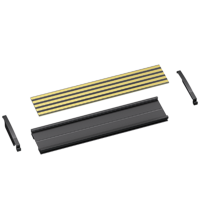
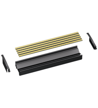
Associated Products: S1SD-1DI-1R
| Matching System Components | ||||||
|---|---|---|---|---|---|---|
|
||||||
|
||||||
|
||||||
|
||||||
|
||||||
 Contact Us


Pepperl+Fuchs Inc.
1600 Enterprise Parkway
Twinsburg, OH 44087
United States of America
sales@us.pepperl-fuchs.com
 +1 330 425-3555
Pepperl+Fuchs is a leading developer and manufacturer of electronic sensors and components for the global automation market. Continuous innovation, enduring quality, and steady growth have been the foundation of our success for more than 70 years. Pepperl+Fuchs employs 6,300 people worldwide and has manufacturing facilities in Germany, USA, Singapore, Hungary, Indonesia and Vietnam, most of them ISO 9001 certified. Pepperl+Fuchs does not sell personal data.