

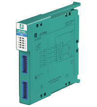
Digital Input LB1109A
- 8-channel
- Inputs Ex ia
- Mounting in Zone 2, Class I/Div.2 or in the safe area
- Dry contact or NAMUR inputs
- Positive or negative logic selectable
- Simulation mode for service operations (forcing)
- Line fault detection (LFD)
- Permanently self-monitoring
- Module can be exchanged under voltage


 Contact Us
Please note: All product-related documents, such as certificates, declarations of conformity, etc., which were issued prior to the conversion under the name Pepperl+Fuchs GmbH or Pepperl+Fuchs AG, also apply to Pepperl+Fuchs SE.
Datasheet excerpt: Technical data of LB1109A
| Slots | ||
|---|---|---|
| Occupied slots | 1 | |
| Supply | ||
| Connection | backplane bus | |
| Rated voltage | 12 V DC , only in connection with the power supplies LB9*** | |
| Power dissipation | 1.55 W | |
| Power consumption | 1.55 W | |
| Internal bus | ||
| Connection | backplane bus | |
| Interface | manufacturer-specific bus to standard com unit | |
| Digital input | ||
| Number of channels | 8 | |
| Sensor interface | ||
| Connection | NAMUR sensor | |
| Connection [2] | volt-free contact | |
| Connection | Terminals 1+, 2-, 3+, 4-, 5+, 6-, 7+, 8-, 9+, 10-, 11+, 12-, 13+,14-, 15+, 16- | |
| Rated values | acc. to EN 60947-5-6 (NAMUR) | |
| Switching point/switching hysteresis | 1.2 ... 2.1 mA / ± 0.2 mA | |
| Voltage | 8.2 V | |
| Internal resistor | 1 kΩ | |
| Line fault detection | can be switched on/off for each channel via configuration tool | |
| Connection | mechanical switch with additional resistors (see connection diagram) proximity sensors without additional wiring | |
| Short-circuit | < 360 Ω | |
| Open-circuit | < 0.35 mA | |
| Minimum pulse duration | 15 ms | |
| Indicators/settings | ||
| LED indication | Power LED (P) green: supply Diagnostic LED (I) red: module fault , red flashing: communication error , white: fixed parameter set (parameters from com unit are ignored) , white flashing: requests parameters from com unit Status LED (1-8) red: line fault (lead breakage or short circuit) , yellow: signal (per channel) |
|
| Coding | optional mechanical coding via front socket | |
| Directive conformity | ||
| Electromagnetic compatibility | ||
| Directive 2014/30/EU | EN 61326-1:2013 | |
| Conformity | ||
| Electromagnetic compatibility | NE 21 | |
| Degree of protection | IEC 60529 | |
| Environmental test | EN 60068-2-14 | |
| Shock resistance | EN 60068-2-27 | |
| Vibration resistance | EN 60068-2-6 | |
| Damaging gas | EN 60068-2-42 | |
| Relative humidity | EN 60068-2-78 | |
| Ambient conditions | ||
| Ambient temperature | -40 ... 60 °C (-40 ... 140 °F) | |
| Storage temperature | -40 ... 85 °C (-40 ... 185 °F) | |
| Relative humidity | 95 % non-condensing | |
| Altitude | max. 2000 m | |
| Shock resistance | shock type I, shock duration 11 ms, shock amplitude 15 g, number of shocks 18 | |
| Vibration resistance | frequency range 10 ... 150 Hz; transition frequency: 57.56 Hz, amplitude/acceleration ± 0.075 mm/1 g; 10 cycles frequency range 5 ... 100 Hz; transition frequency: 13.2 Hz amplitude/acceleration ± 1 mm/0.7 g; 90 minutes at each resonance |
|
| Damaging gas | designed for operation in environmental conditions acc. to ISA-S71.04-1985, severity level G3 | |
| Mechanical specifications | ||
| Degree of protection | IP20 when mounted on backplane | |
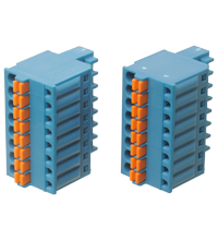
| Connection | removable front connector with spring terminal (0.14 ... 0.5 mm2) | |
| Mass | approx. 90 g | |
| Dimensions | 16 x 100 x 102 mm (0.63 x 3.9 x 4 inch) | |
| Data for application in connection with hazardous areas | ||
| EU-type examination certificate | EXA 13 ATEX 0036X | |
| Marking |  II 3(1) G Ex nA [ia Ga] IIC T4 Gc I (M1) [Ex ia Ma] I II (1) D [Ex ia Da] IIIC II 3(1) G Ex nA [ia Ga] IIC T4 Gc I (M1) [Ex ia Ma] I II (1) D [Ex ia Da] IIIC |
|
| Input | ||
| Voltage | 10 V | |
| Current | 13 mA | |
| Power | 33 mW (linear characteristic) | |
| Galvanic isolation | ||
| Input/power supply, internal bus | safe electrical isolation acc. to EN 60079-11, voltage peak value 375 V | |
| Directive conformity | ||
| Directive 2014/34/EU | EN IEC 60079-0:2018+AC:2020 EN 60079-11:2012 EN 60079-15:2010 |
|
| International approvals | ||
| ATEX approval | EXA 13 ATEX 0036X | |
| UL approval | E106378 | |
| IECEx approval | ||
| IECEx certificate | IECEx EXA 13.0003X | |
| IECEx marking | Ex nA [ia Ga] IIC T4 Gc [Ex ia Da] IIIC [Ex ia Ma] I |
|
| General information | ||
| System information | The module has to be mounted in appropriate backplanes (LB9***) in Zone 2 or outside hazardous areas. Here, observe the corresponding declaration of conformity. For use in hazardous areas (e. g. Zone 2, Zone 22 or Div. 2) the module must be installed in an appropriate enclosure. |
|
| Supplementary information | EC-Type Examination Certificate, Statement of Conformity, Declaration of Conformity, Attestation of Conformity and instructions have to be observed where applicable. For information see www.pepperl-fuchs.com. | |
Classifications
| System | Classcode |
|---|---|
| ECLASS 13.0 | 27210121 |
| ECLASS 12.0 | 27210121 |
| ECLASS 11.0 | 27210121 |
| ECLASS 10.0.1 | 27210121 |
| ECLASS 9.0 | 27210121 |
| ECLASS 8.0 | 27210121 |
| ECLASS 5.1 | 27210120 |
| ETIM 9.0 | EC001485 |
| ETIM 8.0 | EC001485 |
| ETIM 7.0 | EC001485 |
| ETIM 6.0 | EC001485 |
| ETIM 5.0 | EC001485 |
| UNSPSC 12.1 | 39121008 |
Details: LB1109A
The device accepts digital input signals of NAMUR sensors or mechanical contacts from the hazardous area.
Open and short circuit line faults are detected.
The inputs are galvanically isolated from the bus and the power supply.
Datasheet: LB1109A
| Datasheet | File Type | File Size |
|---|---|---|
| Datasheet LB1109A | 660 KB | |
| Datenblatt LB1109A | 662 KB |
Documents: LB1109A
CAD+CAE: LB1109A
| CAD | File Type | File Size |
|---|---|---|
| CAD 3-D / CAD 3-D | STP | 1453 KB |
| CAD Portal / CAD Portal | LINK | --- |
| EPLAN | ||
| CAE EPLAN Data Portal / CAE EPLAN Data Portal | LINK | --- |
| CAE EPLAN macro EDZ / CAE EPLAN Makro EDZ | EDZ | 1763 KB |
Approvals+Certificates: LB1109A
| Certificates | File Type | File Size |
|---|---|---|
| Brasil TUV Rheinland Brazil | 1224 KB | |
| Bureau Veritas (Maritime) Marine | 590 KB | |
| Canada UL cUL | LINK | --- |
| China SITIIAS CCC Ex Certificate | 1374 KB | |
| DNV Marine | 110 KB | |
| EXA IECEx Certificate of Conformity Non-Sparking nA | LINK | --- |
| Europe EXA ATEX Category (1) D ATEX Category (M1) ATEX Category 3 G | 403 KB | |
| Lloyd's Register Marine | 557 KB | |
| South Africa MASC | 730 KB | |
| USA Canada, USA UL Certificate of Compliance cULus | 570 KB | |
| USA UL | LINK | --- |
| United Kingdom CML UKEX Category (1) D UKEX Category (M1) UK-Type Examination Certificate UKEX Category 3 (1) G | 187 KB | |
| Control Drawings | ||
| Control drawing CSA / Control drawing CSA | 225 KB | |
| Declaration of Conformity | ||
| EU Declaration of Conformity (P+F) / EU-Konformitäterklärung (P+F) | 1143 KB | |
| UK Declaration of Conformity (P+F) / UK-Konformitäterklärung (P+F) | 1038 KB |
Associated Products: LB1109A
| Accessories | ||||||
|---|---|---|---|---|---|---|
|
||||||

- Ask an Expert
- Cross Reference Request
- Check order status
- News
- NetPartner Login
- Subscribe to Gate-Way, our Process Automation Division e-newsletter
- Service Level Agreements for ecom instruments
- Find a Local Distributor or Representative
- Literature
- Technologies
- Control System Solutions
- Download Technical Documents
- Press Releases
- International Trade Shows
The new LB/FB PROFINET gateways from Pepperl+Fuchs open the door for IIoT 4.0 applications in process industries.


Pepperl+Fuchs Inc.
1600 Enterprise Parkway
Twinsburg, OH 44087
United States of America
sales@us.pepperl-fuchs.com
 +1 330 425-3555
Pepperl+Fuchs is a leading developer and manufacturer of electronic sensors and components for the global automation market. Continuous innovation, enduring quality, and steady growth have been the foundation of our success for more than 70 years. Pepperl+Fuchs employs 6,300 people worldwide and has manufacturing facilities in Germany, USA, Singapore, Hungary, Indonesia and Vietnam, most of them ISO 9001 certified. Pepperl+Fuchs does not sell personal data.