

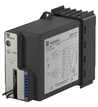
Digital Output with Shutdown Input FB6210ER
- 4-channel
- Outputs Ex ia
- Installation in suitable enclosures in Zone 1
- Module can be exchanged under voltage (hot swap)
- Line fault detection (LFD)
- Positive or negative logic selectable
- Simulation mode for service operations (forcing)
- Permanently self-monitoring
- Output with watchdog
- Output with bus-independent safety shutdown input


 Contact Us
Please note: All product-related documents, such as certificates, declarations of conformity, etc., which were issued prior to the conversion under the name Pepperl+Fuchs GmbH or Pepperl+Fuchs AG, also apply to Pepperl+Fuchs SE.
Datasheet excerpt: Technical data of FB6210ER
| Slots | ||
|---|---|---|
| Occupied slots | 2 | |
| Functional safety related parameters | ||
| Safety Integrity Level (SIL) | SIL 2 | |
| Supply | ||
| Connection | backplane bus / booster terminals | |
| Rated voltage | 12 V DC , only in connection with the power supplies FB92** | |
| Input voltage range | 18.5 ... 32 V DC (SELV/PELV) booster voltage | |
| Power dissipation | 3 W | |
| Power consumption | 0.15 W | |
| Internal bus | ||
| Connection | backplane bus | |
| Interface | manufacturer-specific bus to standard com unit | |
| Digital output | ||
| Number of channels | 4 | |
| Suitable field devices | ||
| Field device | Solenoid Valve | |
| Field device [2] | audible alarm | |
| Field device [3] | visual alarm | |
| Connection | channel I: 9+, 10-; channel II: 11+, 12-; channel III: 13+, 14-; channel IV: 15+, 16- | |
| Internal resistor | max. 370 Ω | |
| Current limit | 37 mA | |
| Open loop voltage | 24.5 V | |
| Line fault detection | can be switched on/off for each channel via configuration tool also when turned off (every 2.5 s the valve is turned on for 2 ms) | |
| Short-circuit | < 100 Ω | |
| Open-circuit | > 15 kΩ | |
| Response time | 10 ms (depending on bus cycle time) | |
| Watchdog | within 0.5 s the device goes in safe state, e.g. after loss of communication | |
| Reaction time | 10 s | |
| Indicators/settings | ||
| LED indication | LED green: supply LED red: line fault , red flashing: communication error |
|
| Coding | optional mechanical coding via front socket | |
| Directive conformity | ||
| Electromagnetic compatibility | ||
| Directive 2014/30/EU | EN 61326-1 | |
| Conformity | ||
| Electromagnetic compatibility | NE 21 | |
| Degree of protection | IEC 60529 | |
| Environmental test | EN 60068-2-14 | |
| Shock resistance | EN 60068-2-27 | |
| Vibration resistance | EN 60068-2-6 | |
| Damaging gas | EN 60068-2-42 | |
| Relative humidity | EN 60068-2-78 | |
| Ambient conditions | ||
| Ambient temperature | -20 ... 60 °C (-4 ... 140 °F) | |
| Storage temperature | -25 ... 85 °C (-13 ... 185 °F) | |
| Relative humidity | 95 % non-condensing | |
| Shock resistance | shock type I, shock duration 11 ms, shock amplitude 15 g, number of shocks 18 | |
| Vibration resistance | frequency range 10 ... 150 Hz; transition frequency: 57.56 Hz, amplitude/acceleration ± 0.075 mm/1 g; 10 cycles frequency range 5 ... 100 Hz; transition frequency: 13.2 Hz amplitude/acceleration ± 1 mm/0.7 g; 90 minutes at each resonance |
|
| Damaging gas | designed for operation in environmental conditions acc. to ISA-S71.04-1985, severity level G3 | |
| Mechanical specifications | ||
| Degree of protection | IP20 (module) , a separate housing is required acc. to the system description | |
| Connection | removable front connector with screw flange (accessory) wiring connection via spring terminals (0.14 ... 1.5 mm2) or screw terminals (0.08 ... 1.5 mm2) |
|
| Mass | approx. 750 g | |
| Dimensions | 57 x 107 x 132 mm (2.2 x 4.2 x 5.2 inch) | |
| Data for application in connection with hazardous areas | ||
| EU-type examination certificate | PTB 97 ATEX 1074 U | |
| Marking |  II 2(1) G Ex d [ia Ga] IIC Gb II (1) D [Ex ia Da] IIIC II 2(1) G Ex d [ia Ga] IIC Gb II (1) D [Ex ia Da] IIIC |
|
| Output | ||
| Voltage | 27.8 V | |
| Current | 90.4 mA | |
| Power | 629 mW | |
| Internal capacitance | 2.5 nF | |
| Internal inductance | 0 mH | |
| Galvanic isolation | ||
| Output/power supply, internal bus | safe electrical isolation acc. to EN 60079-11, voltage peak value 375 V | |
| Directive conformity | ||
| Directive 2014/34/EU | EN 60079-0:2009 EN 60079-1:2007 EN 60079-11:2007 EN 60079-26:2007 EN 61241-11:2006 |
|
| International approvals | ||
| ATEX approval | PTB 97 ATEX 1075 ; PTB 97 ATEX 1074 U |
|
| EAC approval | Russia: RU C-IT.MIII06.B.00129 | |
| Marine approval | ||
| Lloyd Register | 15/20021 | |
| DNV GL Marine | TAA0000034 | |
| American Bureau of Shipping | T1450280/UN | |
| Bureau Veritas Marine | 22449/B0 BV | |
| General information | ||
| System information | The module has to be mounted in appropriate backplanes and housings (FB92**) in Zone 1, 2, 21, 22 or outside hazardous areas (gas or dust). Here, observe the corresponding EC-type examination certificate. | |
| Supplementary information | EC-Type Examination Certificate, Statement of Conformity, Declaration of Conformity, Attestation of Conformity and instructions have to be observed where applicable. For information see www.pepperl-fuchs.com. | |
Classifications
| System | Classcode |
|---|---|
| ECLASS 13.0 | 27210101 |
| ECLASS 12.0 | 27210101 |
| ECLASS 11.0 | 27210101 |
| ECLASS 10.0.1 | 27210101 |
| ECLASS 9.0 | 27210101 |
| ECLASS 8.0 | 27210101 |
| ECLASS 5.1 | 27210120 |
| ETIM 9.0 | EC001485 |
| ETIM 8.0 | EC001485 |
| ETIM 7.0 | EC001485 |
| ETIM 6.0 | EC001485 |
| ETIM 5.0 | EC001485 |
| UNSPSC 12.1 | 39121008 |
Details: FB6210ER
The digital output features 4 independent channels.
The device can be used to drive solenoids, sounders, or LEDs.
Open and short-circuit line faults are detected.
The outputs are galvanically isolated from the bus and the power supply.
The output can be switched off via a contact. This can be used for bus-independent safety applications.
Datasheet: FB6210ER
| Datasheet | File Type | File Size |
|---|---|---|
| Datasheet FB6210ER | 830 KB | |
| Datenblatt FB6210ER | 831 KB |
Documents: FB6210ER
Approvals+Certificates: FB6210ER

- Ask an Expert
- Cross Reference Request
- Check order status
- News
- NetPartner Login
- Subscribe to Gate-Way, our Process Automation Division e-newsletter
- Service Level Agreements for ecom instruments
- Find a Local Distributor or Representative
- Literature
- Technologies
- Control System Solutions
- Download Technical Documents
- Press Releases
- International Trade Shows


Pepperl+Fuchs Inc.
1600 Enterprise Parkway
Twinsburg, OH 44087
United States of America
sales@us.pepperl-fuchs.com
 +1 330 425-3555
Pepperl+Fuchs is a leading developer and manufacturer of electronic sensors and components for the global automation market. Continuous innovation, enduring quality, and steady growth have been the foundation of our success for more than 70 years. Pepperl+Fuchs employs 6,300 people worldwide and has manufacturing facilities in Germany, USA, Singapore, Hungary, Indonesia and Vietnam, most of them ISO 9001 certified. Pepperl+Fuchs does not sell personal data.