

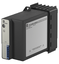
Com Unit for PROFIBUS DP/DP-V1 FB8205*
- Interface between the I/O modules and the PCS/PLC
- Com unit for 80 analog or 184 digital channels
- Communication via PROFIBUS DP
- Module can be exchanged under voltage (hot swap)
- Installation in suitable enclosures in Zone 1
- HART communication via PROFIBUS DP V1 or service bus
- Configuration via FDT 1.2 DTM
- Non-volatile memory for configuration and parameter settings
- Self configuration in redundant systems
- Permanently self-monitoring
- Outputs drive to safe state in case of failures


 Contact Us
Please note: All product-related documents, such as certificates, declarations of conformity, etc., which were issued prior to the conversion under the name Pepperl+Fuchs GmbH or Pepperl+Fuchs AG, also apply to Pepperl+Fuchs SE.
Datasheet excerpt: Technical data of FB8205*
| Supply | ||
|---|---|---|
| Connection | backplane bus | |
| Rated voltage | 5 V DC , only in connection with the power supplies FB92** | |
| Power consumption | 2 W | |
| Fieldbus connection | ||
| Fieldbus type | PROFIBUS DP/DP-V1 | |
| PROFIBUS DP | ||
| Connection | wired to Ex e terminals via backplane | |
| Baud rate | up to 1.5 MBit/s | |
| Protocol | PROFIBUS DP/DP V1 read/write services | |
| Number of stations per bus line | max. 125 (PROFIBUS), max. 119 (service bus) | |
| Cyclic process data | 240 bytes in total, either input or output data | |
| Number of stations per bus segment | max. 31 (RS-485 standard) | |
| Number of repeaters between Master and Slave | max. 3 | |
| Supported I/O modules | all FB remote I/O modules | |
| Bus length | max. 1000 m (FOL, 1.5 MBaud), max. 1000 m (copper cable, 187.5 kBd), max. 200 m (copper cable, 1.5 MBd) |
|
| Addressing | via configuration software | |
| PROFIBUS address | 0 ... 126 (factory standard setting: 126) |
|
| GSE file | CGV61710.gsd/gse | |
| HART communication | via PROFIBUS or service bus | |
| Internal bus | ||
| Connection | backplane bus | |
| Redundancy | via front connector | |
| Indicators/settings | ||
| LED indicator | LED green (power supply): On = operating, fast flash = cold start, slow flash = HCIR loading active LED red (collective alarm): On = internal fault, flashing = no PROFIBUS connection LED yellow (operating mode): flashing 1 (1:1 ratio) = active, normal operation; flashing 2 (7:1 ratio) = active, simulation |
|
| Directive conformity | ||
| Electromagnetic compatibility | ||
| Directive 2014/30/EU | EN 61326-1 | |
| Conformity | ||
| Electromagnetic compatibility | NE 21 | |
| Degree of protection | IEC 60529 | |
| Ambient conditions | ||
| Ambient temperature | -20 ... 60 °C (-4 ... 140 °F) | |
| Storage temperature | -25 ... 85 °C (-13 ... 185 °F) | |
| Relative humidity | 95 % non-condensing | |
| Shock resistance | shock type I, shock duration 11 ms, shock amplitude 15 g, number of shocks 18 | |
| Vibration resistance | frequency range 10 ... 150 Hz; transition frequency: 57.56 Hz, amplitude/acceleration ± 0.075 mm/1 g; 10 cycles frequency range 5 ... 100 Hz; transition frequency: 13.2 Hz amplitude/acceleration ± 1 mm/0.7 g; 90 minutes at each resonance |
|
| Damaging gas | designed for operation in environmental conditions acc. to ISA-S71.04-1985, severity level G3 | |
| Mechanical specifications | ||
| Degree of protection | IP20 (module) , a separate housing is required acc. to the system description | |
| Connection | via backplane | |
| Mass | approx. 750 g | |
| Dimensions | 57 x 107 x 132 mm (2.2 x 4.2 x 5.2 inch) | |
| Data for application in connection with hazardous areas | ||
| EU-Type Examination Certificate | PTB 97 ATEX 1074 U | |
| Marking |  II 2(1) G Ex d [ia Ga] IIC Gb II 2(1) G Ex d [ia Ga] IIC Gb |
|
| Directive conformity | ||
| Directive 2014/34/EU | EN 60079-0:2009 EN 60079-1:2007 EN 60079-11:2007 EN 60079-26:2007 EN 61241-11:2006 |
|
| International approvals | ||
| ATEX approval | PTB 97 ATEX 1075 |
|
| EAC approval | Russia: RU C-IT.MIII06.B.00129 | |
| Marine approval | ||
| Lloyd Register | 15/20021 | |
| DNV GL Marine | TAA0000034 | |
| American Bureau of Shipping | T1450280/UN | |
| Bureau Veritas Marine | 22449/B0 BV | |
Classifications
| System | Classcode |
|---|---|
| ECLASS 13.0 | 27210121 |
| ECLASS 12.0 | 27210121 |
| ECLASS 11.0 | 27210121 |
| ECLASS 10.0.1 | 27210121 |
| ECLASS 9.0 | 27210121 |
| ECLASS 8.0 | 27210121 |
| ECLASS 5.1 | 27210121 |
| ETIM 9.0 | EC001485 |
| ETIM 8.0 | EC001485 |
| ETIM 7.0 | EC001485 |
| ETIM 6.0 | EC001485 |
| ETIM 5.0 | EC001485 |
| UNSPSC 12.1 | 39121008 |
Details: FB8205*
The PROFIBUS com unit forms the interface between the I/O modules on the backplane and the process control system.
It supports all single width and dual width I/O modules. Thereby signals from NAMUR sensors, mechanical contacts, high-power solenoid drivers, power relays, sounders, and alarm LEDs are transported to the higher-level bus system.
The com unit can be easily configured via DTM and supports redundancy as well as HART.
Datasheet: FB8205*
| Datasheet | File Type | File Size |
|---|---|---|
| Datasheet FB8205* | 575 KB | |
| Datenblatt FB8205* | 576 KB |
Documents: FB8205*
CAD+CAE: FB8205*
| EPLAN | File Type | File Size |
|---|---|---|
| CAE EPLAN Data Portal / CAE EPLAN Data Portal | LINK | --- |
| CAE EPLAN macro EDZ / CAE EPLAN Makro EDZ | EDZ | 144 KB |
Approvals+Certificates: FB8205*
Software: FB8205*
| Device Driver | File Type | File Size |
|---|---|---|
| EDS file for Simatic PDM 5.xx and 6.xx / EDS-Datei für Simatic PDM 5.xx und 6.xx | ZIP | 550 KB |
| GSE 1710 / GSD 1710 | ZIP | 8 KB |
| Device type managers (DTM) | ||
| DTM Collection Remote IO / DTM Collection Remote IO | ZIP | 47727 KB |
| Software Tools | ||
| Tools to configure LB/FB Remote I/O without DTM / Tools zur LB/FB-Remote-I/O-Konfiguration ohne DTM | ZIP | 51019 KB |
| Firmware | ||
| Service-Tool / Service-Tool | ZIP | 5185 KB |
Associated Products: FB8205*
| Accessories | ||||||
|---|---|---|---|---|---|---|
|
||||||


- Ask an Expert
- Cross Reference Request
- Check order status
- News
- NetPartner Login
- Subscribe to Gate-Way, our Process Automation Division e-newsletter
- Service Level Agreements for ecom instruments
- Find a Local Distributor or Representative
- Literature
- Technologies
- Control System Solutions
- Download Technical Documents
- Press Releases
- International Trade Shows


Pepperl+Fuchs Inc.
1600 Enterprise Parkway
Twinsburg, OH 44087
United States of America
sales@us.pepperl-fuchs.com
 +1 330 425-3555
Pepperl+Fuchs is a leading developer and manufacturer of electronic sensors and components for the global automation market. Continuous innovation, enduring quality, and steady growth have been the foundation of our success for more than 70 years. Pepperl+Fuchs employs 6,300 people worldwide and has manufacturing facilities in Germany, USA, Singapore, Hungary, Indonesia and Vietnam, most of them ISO 9001 certified. Pepperl+Fuchs does not sell personal data.