

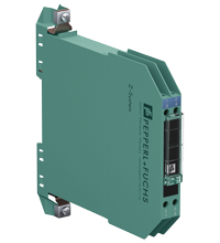
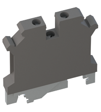
Zener Barrier Z896
- 2-channel
- DC version, negative polarity
- Working voltage 24 V/18 V at 10 µA
- Series resistance max. 340 Ω/437 Ω
- Fuse rating 50 mA
- DIN rail mountable
- Asymmetrical version


 Contact Us
Please note: All product-related documents, such as certificates, declarations of conformity, etc., which were issued prior to the conversion under the name Pepperl+Fuchs GmbH or Pepperl+Fuchs AG, also apply to Pepperl+Fuchs SE.
Datasheet excerpt: Technical data of Z896
| Search characteristics | ||
|---|---|---|
| Additional functions | ||
| Asymmetrical version | yes | |
| General specifications | ||
| Type | DC version, negative polarity | |
| Electrical specifications | ||
| Nominal resistance | terminals 1, 8: 320 Ω terminals 4, 5: 415 Ω |
|
| Series resistance | terminals 1, 8: max. 340 Ω terminals 4, 5: max. 437 Ω |
|
| Fuse rating | 50 mA | |
| Hazardous area connection | ||
| Connection | terminals 1, 2; 3, 4 | |
| Safe area connection | ||
| Connection | terminals 5, 6; 7, 8 | |
| Working voltage | ||
| Supply loop | terminals 7, 8: max. 24.6 V terminals 5, 6: max. 19 V |
|
| Measurement loop | terminals 7, 8: max. 24 V at 10 µA terminals 5, 6: max. 18 V at 10 µA |
|
| Conformity | ||
| Degree of protection | IEC 60529 | |
| Ambient conditions | ||
| Ambient temperature | -20 ... 60 °C (-4 ... 140 °F) | |
| Storage temperature | -25 ... 70 °C (-13 ... 158 °F) | |
| Relative humidity | max. 75 % , without condensation | |
| Mechanical specifications | ||
| Degree of protection | IP20 | |
| Connection | screw terminals | |
| Core cross section | max. 2 x 2.5 ... mm2 | |
| Mass | approx. 150 g | |
| Dimensions | 12.5 x 115 x 116 mm (0.5 x 4.5 x 4.6 inch) (W x H x D) | |
| Height | 115 mm | |
| Width | 12.5 mm | |
| Depth | 116 mm | |
| Construction type | modular terminal housing , see system description | |
| Mounting | on 35 mm DIN mounting rail acc. to EN 60715:2001 | |
| Data for application in connection with hazardous areas | ||
| EU-type examination certificate | BAS 01 ATEX 7005 | |
| Marking |  II (1)GD, I (M1) [Ex ia Ga] IIC, [Ex ia Da] IIIC, [Ex ia Ma] I II (1)GD, I (M1) [Ex ia Ga] IIC, [Ex ia Da] IIIC, [Ex ia Ma] I |
|
| Voltage | terminals 1, 2: 26.6 V; terminals 3, 4: 20.5 V | |
| Current | terminals 1, 2: 85 mA; terminals 3, 4: 50 mA | |
| Power | terminals 1, 2: 560 mW; terminals 3, 4: 260 mW | |
| Supply | ||
| Maximum safe voltage | 250 V | |
| Series resistance | terminals 1, 2: min. 314 Ω; terminals 3, 4: min. 407 Ω | |
| Certificate | TÜV 99 ATEX 1484 X | |
| Marking | II 3G Ex nA IIC T4 Gc |
|
| Directive conformity | ||
| Directive 2014/34/EU | EN IEC 60079-0:2018+AC:2020 , EN 60079-11:2012 , EN 60079-15:2010 | |
| International approvals | ||
| FM approval | ||
| Control drawing | 116-0118 | |
| UL approval | ||
| Control drawing | 116-0139 (cULus) | |
| IECEx approval | ||
| IECEx certificate | IECEx BAS 09.0142 IECEx BAS 17.0091X |
|
| IECEx marking | [Ex ia Ga] IIC , [Ex ia Da] IIIC , [Ex ia Ma] I Ex ec IIC T4 Gc |
|
| General information | ||
| Supplementary information | Observe the certificates, declarations of conformity, instruction manuals, and manuals where applicable. For information see www.pepperl-fuchs.com. | |
Classifications
| System | Classcode |
|---|---|
| ECLASS 13.0 | 27211016 |
| ECLASS 12.0 | 27211016 |
| ECLASS 11.0 | 27211016 |
| ECLASS 10.0.1 | 27219001 |
| ECLASS 9.0 | 27219001 |
| ECLASS 8.0 | 27219001 |
| ECLASS 5.1 | 27210702 |
| ETIM 9.0 | EC001485 |
| ETIM 8.0 | EC001485 |
| ETIM 7.0 | EC001485 |
| ETIM 6.0 | EC001485 |
| ETIM 5.0 | EC002653 |
| UNSPSC 12.1 | 39121018 |
Details: Z896
The Zener Barrier prevents the transfer of unacceptably high energy from the safe area into the hazardous area.
The zener diodes in the Zener Barrier are connected in the reverse direction. The breakdown voltage of the diodes is not exceeded in normal operation. If this voltage is exceeded, due to a fault in the safe area, the diodes start to conduct, causing the fuse to blow. The Zener Barrier has a negative polarity, i. e. the cathodes of the zener diodes are grounded.
Asymmetrical Zener Barriers are for optimization of applications which have different voltage levels regarding to ground potential.
Depending on the application, increased or decreased intrinsic safety parameters apply for serial or parallel connection. For the detailed parameters refer to the Zener Barrier certificate. Application examples can be found in the system description of the Zener Barriers.
Datasheet: Z896
| Datasheet | File Type | File Size |
|---|---|---|
| Datasheet Z896 | 966 KB | |
| Fiche de données Z896 | 969 KB | |
| Datenblatt Z896 | 967 KB | |
| Datasheet Z896 | 973 KB | |
| Hoja de datos Z896 | 968 KB |
Documents: Z896
| Manuals | File Type | File Size |
|---|---|---|
| System Manual | 1203 KB | |
| Systemhandbuch | 1203 KB | |
| Instruction manuals | ||
| Инструкции | 233 KB | |
| Instruction manual / Betriebsanleitung | 331 KB | |
| Návod k poużití | 229 KB | |
| Instruktions manual | 227 KB | |
| Instruction manual | 233 KB | |
| Kasutusjuhend | 223 KB | |
| Käyttöohje | 223 KB | |
| Manuel d'instructions | 230 KB | |
| Betriebsanleitung | 233 KB | |
| Οδηγίες χρήσης | 236 KB | |
| Handleiding | 228 KB | |
| Instruction manual / Betriebsanleitung | 227 KB | |
| Használati útmutató | 229 KB | |
| Manuale di istruzioni | 228 KB | |
| Lietošanas pamācība | 227 KB | |
| Instrukciju vadovas | 228 KB | |
| Instrukcja obsługi | 230 KB | |
| Manual de instruções | 229 KB | |
| Manual de utilizare | 228 KB | |
| Návod na poużitie | 228 KB | |
| Navodila za uporabo | 226 KB | |
| Manual de instrucciones | 229 KB | |
| Manual | 225 KB | |
| Documents | ||
| Functional Safety Manual | 1972 KB | |
| Handbuch Funktionale Sicherheit | 1938 KB |
CAD+CAE: Z896
| CAD | File Type | File Size |
|---|---|---|
| CAD 3-D / CAD 3-D | STP | 951 KB |
| CAD Portal / CAD Portal | LINK | --- |
| EPLAN | ||
| EPLAN macros Z-System devices (EMA) / EPLAN-Makros Geräte Z-System (EMA) | ZIP | 2338 KB |
Approvals+Certificates: Z896
Associated Products: Z896
| Matching System Components | ||||||
|---|---|---|---|---|---|---|
|
||||||
|
||||||
|
||||||
|
||||||
|
||||||
|
||||||
|
||||||
|
||||||
|
||||||
|
||||||


- Ask an Expert
- Cross Reference Request
- Check order status
- News
- NetPartner Login
- Subscribe to Gate-Way, our Process Automation Division e-newsletter
- Service Level Agreements for ecom instruments
- Find a Local Distributor or Representative
- Literature
- Technologies
- Control System Solutions
- Download Technical Documents
- Press Releases
- International Trade Shows


Pepperl+Fuchs Inc.
1600 Enterprise Parkway
Twinsburg, OH 44087
United States of America
sales@us.pepperl-fuchs.com
 +1 330 425-3555
Pepperl+Fuchs is a leading developer and manufacturer of electronic sensors and components for the global automation market. Continuous innovation, enduring quality, and steady growth have been the foundation of our success for more than 70 years. Pepperl+Fuchs employs 6,300 people worldwide and has manufacturing facilities in Germany, USA, Singapore, Hungary, Indonesia and Vietnam, most of them ISO 9001 certified. Pepperl+Fuchs does not sell personal data.